
Whatsapp: +8615936220108
Email: [email protected]

Whatsapp: +8615936220108
Email: [email protected]
News
1.The general requirements
(1)The technical requirements for installation shall comply with the relevant provisions of GB50278 Code for Construction and Acceptance of Lifting Equipment Installation Engineering.
(2)Rods or components connected by bolts or pins must be marked with positions and connected in place according to the structural installation position marking diagram. They must not be used interchangeably.
(3) Use bolts, nuts and washers correctly according to the type, strength level and length shown at each connection point in the general assembly drawing of the components.
(4) Check whether the parts have deformation, rust and other defects, and to eliminate.
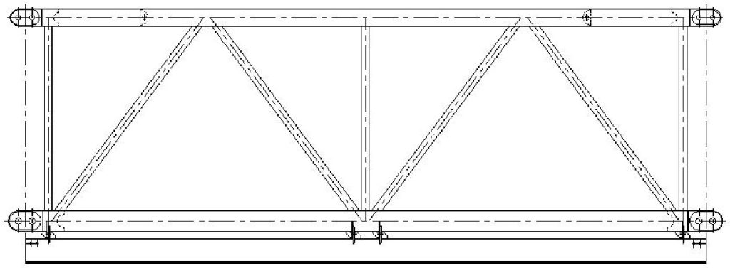
2. Installation of main girder and related components
(1)The complete assembled lifting mechanism is hang into corresponding position in the left bridge and then tight the frame foot bolt and weld the stopper.
(2)The complete assembled traction mechanism is hang into corresponding position in the left bridge and then tight the frame foot bolt and weld the stopper.
(3)Removable horizontal lever which above the left bridge frame is connected with bolts.
(4)First clean the chord of the butt joint, impurities and corrosion of ear hole, it shall be no oil paint on the ear plate.Assemble the main girder segments on the site of the sleeper according to the parts mark of mounting position of the structure in the schematic diagram (mark at the time of pre assembly).The girder segments should be assembled, the ear plate girder section chord connecting pin(To facilitate the removal of the pin shaft, the shaft hole and pin can be properly painted with butter).In order to facilitate the installation of the shaft end positioning spring pin, the shaft pin hole should be horizontal position when the pin is passed.The ear plate pin must be connected after adjusting the connecting lug (ensure rail height and lateral deviation).The connected segment shall not be connected to the unsupported state after connecting completion of pin of ear plate of bottom chord and before connecting completion of pin of ear plate of upper chord.Complete the assembly of all the main girders. Connection pretightening force of girder segments the ear plate is not less than 100kN.
(5) The complete left guide pulley, right guide pulley and wire rope are fixed in the corresponding position.The pin of the ear plate of the bottom chord must be connected first when the main beam assembly.
3.Installation of electric hoist assembly
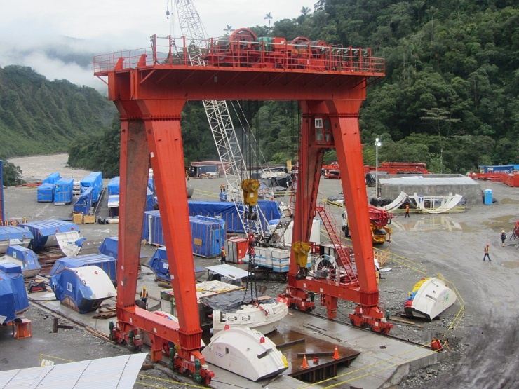
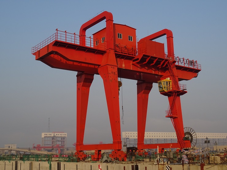
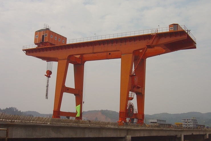
(1)The assembled girder is padded 2m, the support and the situation on the ground does not affect the operating of electric hoist in range of the bridge. In addition, should adopt measures to make the bridge along the longitudinal and transverse fixation.
(2)The electric hoist is assembled on the walking track of the hoist, and then the defects of each cable pulley are checked, and the double nuts of the wheel shaft end are tightened again,the cable pulley is pushed into the track from the left end of the calabash walking track
(3)Fix the cable, the signal line and the pulley cable on the pulley with about 3.6m of the cable between the pulleys,connect cable, signal cable and pulley cable to electric hoist.
(4)Electric hoist will be carried out to the left and right running limit position of the main beam (specific location of the size reference the random MDG40-00.00.00D),Adjust the position of the switch and the position of the lever, so that the electric hoist can be stopped at the working limit and fixed after .At the same time, observe the hoist, the pulley operation in the orbit, the effect of the gourd push rod on the pulley, if there is discomfort, it must be adjusted in a timely.
4.The installation of rigid legs, flexible legs and related components
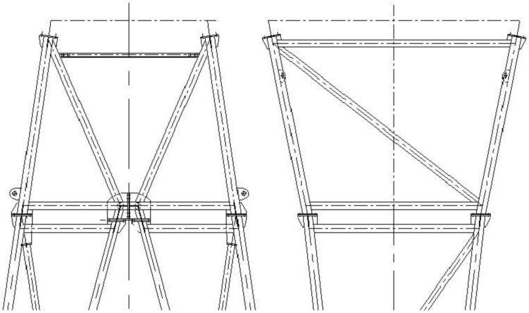
(1)The installation of rigid legs
(2)First, clean up the impurities and rust of the flange surface, the frictional junction surface of chords and web members which can not have oil or paint.The schematic diagram of parts markup tags on the grading of sleepers according to the structure of the installation position(Signature of factory when assembling), preliminary assembly rigid legs parts and connecting rods.Meanwhile according to the installation convenient conditions in the sequence,appropriate to the ladder platform components according to the installation drawing size to connect after adjustment in place.Then measure the dimensions of the upper four flange geometric model, and contrast with the corresponding sizes of main girder,the error is not greater than 2,if meeting the demands connect with all the bolt.The bolt(M20) connection preload force between components of rigid legs should not be less than 100 kn.Finally,the ladder platform components and electrical cabinet are temporarily fixed on the right place of the cab platform and electrical cabinet platform.
(3)The installation of flexible legs and related components.
(4) First, clean up the impurities and rust of the flange surface, the frictional junction surface of chords and web members which can not have oil or paint.The schematic diagram of parts markup tags on the grading of sleepers according to the structure of the installation position(Signature of factory when assembling), preliminary assembly flexible legs parts and connecting rods,upper ear base.Then measure the dimensions of the upper geometric model of two ear base flange, and contrast with the corresponding sizes of main girder,the error is not greater than 2,if meeting the demands connect with all the bolt.The bolt(M20) connection preload force between components of rigid legs should not be less than 100 kn.
We are here to help you
You are welcome to : phone call, Message, Wechat, Email& Seaching us, etc.
Email: [email protected]
Phone / Whatsapp: +8615936220108
/ NewsJun 10, 2025
Jacking principle of JLDS300 jack up machine
/ NewsJun 15, 2024
Jinli Heavy Industry JLD Wind Power Tower CraneOur professional team will reply you as soon as possible.
Submit Request
PDF Request
Simply fill out the form below and the catalog will be available for download!